Key Steps for Achieving Reliable Flow from Hoppers
1) If the material behaviour is adversely affected by extended storage time. For example, if the material goes off, 'cakes', sinters, ferments or degrades in any way, it is necessary to ensure that there are no static regions when the bin contents are discharging. That is unless the total contents are emptied every time before fresh material is put into the container. (Material resting against the wall in the lower regions of a non-mass flow bin will not move until all the material above is emptied. This means that fresh material entered will discharge first, and the first material that was loaded comes out last).
2) If the material is free flowing and is composed of granules or powders of differing size range, it will tend to segregate every time that it flows. Accretion of fractions or different components of blends can give rise to many difficulties, hazards and value and quality issues. Were these to cause operational or quality problems, mass flow is needed to minimise the separation and to generate a degree of re-mixing during the discharge process.
3) If the discharged material has to be in a consistent condition of density, has to avoid being too loose and fluid-like, or is to be metered on a volumetric basis, then a Mass Flow pattern is necessary. Duties such a packing into big bags that need to be stable, discharging to filling machines that must hold a given weight via a volumetric filler, to bag fillers that require a settled density to hold the capacity or to a screw feeder that requires the product to have a consistent density and not loose enough to run through the screw without control, all need Mass Flow feed hoppers.
4) If the material filling into the bin is very fine it can retains air for a long time to maintain a fluid-like state. It may be essential to prevent a core flow channel passing through the contents when the bin is emptied, in order to give time for the fresh material to de-aerate to a stable flow condition. Mass Flow inhibits the tendency for 'flushing', providing that sufficient time elapses for the material that was charged into storage earlier to settle.
5) For cohesive and non-free flowing bulk materials, those that will make a good 'snowball' if compressed in the hand, then the outlet size required to secure reliable discharge is smaller if Mass Flow takes place. If vibration is used to aid discharge any material that does not move during outflow from the container will tend to pack down to a firmer condition that that in which it started. In a mass flow channel the bulk will continually deform and maintain a flow state. Whereas an 'expanded flow' channel secures the outlet benefit of Mass Flow, the non-mass flow region has to be designed on the basis of avoiding the formation of 'ratholes' due to the time-consolidated strength of the bulk material.
6) If there is a changeover of product on a continuous flow system, as with some extruder feeds, than Mass Flow is needed to avoid extended cross contamination of the stock.Mass flow is required for gas counter-flow systems, as with the stripping of volatile gasses from the interstitial voidage, or heating and cooling in continuous flow systems. Mass Flow will secure the most even flow velocity profiles and bulk porosity conditions across the moving bed of solids.
7) If none of these conditions apply, a non-mass flow design may be adopted. This will allow significantly more capacity to be held in limited headroom, and allow a feeder to be used that does not necessarily extract from the total interface region with the hopper. When Mass Flow is specified, any feeder used to discharge the hopper must generate 'live' flow, but not necessarily uniform flow, over the entire outlet connection to the hopper. (A publication by Ajax explains the different global regimes of flow in hoppers, and the various constituent local flow modes. A separate article sets out the benefits and drawbacks of these different patterns. Other technical notes available relate to feeders, powder testing and problems that are commonly encountered in the handling of bulk solids).
8) Make yourself familiar with the full range of conditions of the material to be stored. Secure an officially verified, 'fully representative', sample. Check that the material is of consistent supply, from a homogeneous stock, stable in time and under the full range of relevant operating conditions, or know the reason why. See 'Guide to the Specification of Bulk Materials for Storage and Handling Applications' published by the Process Industries Division of the Institution of Mechanical Engineers'. Secure a range of samples if the material varies, to identify and design around the 'worst' condition appropriate to each part of the equipment. For example, the 'worst' flow condition for the hopper will produce light pressures through the outlet onto a feeder. An outlet size that enables reliable flow with product in its 'worst' flow condition causes the highest pressures through the outlet when in its 'best' condition. Hence, the 'worst' condition for the feeder may be when the product is in its 'best' flow condition.
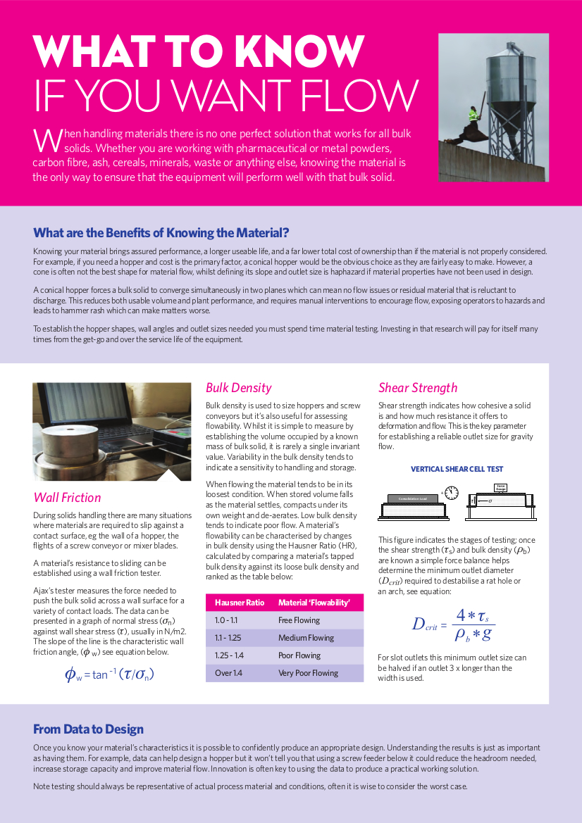
9) Measure wall friction every time. Check with different options of the wall contact material, (inside surface of the hopper wall), if choice allows. Note that the both the surface material and the sample of bulk material must be strictly reflect those prevailing in all concievable operating conditions. Record the measurements for both design and reference. For Mass Flow, wall friction mainly determines the wall inclination required for a given geometric construction. For non-Mass Flow, the value indicates the lowest slope that may be used for the container to self-clear. Record the measurement for both design and reference. Remember that there is no ubiquitous 'Low Friction' material to use for a hopper wall; it depends upon both the product and the contact surface. As wall slip depends almost entirely on wall friction, it is much easier to do something about promoting flow than it is to generate wall slip if the slope of the hopper wall is inadequately steep - hence the crucial role of determining the correct value of friction to get the right hopper angle.
10) If the bulk material has cohesive properties such that it will form a firm compact when compressed, it may develop sufficient strength to hold together and 'arch' or 'bridge' over an outlet. Whether is does or not depends upon many factors, such as the size and shape of the outlet, the degree and time of compaction and whether the flow is of Mass Flow or not. Even if the material does not form a stable arch, it may still form a 'rathole' in a conical hopper, to leave a large proportion of the contents un-discharged. To determine the opening size that will generate reliable flow it is necessary to measure the shear strength of the material in the 'relevant conditions' and apply a design formula. Jenike shear cell testing and the interpretation of results is usually the domain of experts. The 'relevant conditions' means that allowance must be made for extra-normal use. If this outlet size is too large to allow unrestricted flow, a feeder may be fitted to control the feed rate. The choice of feeder interacts with the geometry of the outlet, so the hopper and feeder design is an integral, iterative process that can only be optimised by taking account of all the selection factors involved. It should be noted that flow rate considerations might also influence the size of outlet opening. Measurement of the bulk material permeability is used to assess whether the size of opening limits the discharge rate. See reference 1 for design recommendations.
11) Review the range of operating conditions, including unusual and rare circumstances under which the plant may have to work. Check whether the ambient conditions alter according to production conditions, weather, season or events such as site wash-downs, and allow for these effects on the material to be stored. Circumstances such as restarting operation after shut-downs, holidays, accepting unusual product conditions, or any combination of these that the plant will have to deal with in its working life, may call for a larger orifice size than is needed for use under more normal conditions. Local vibrations tend to strengthen bulk material at rest, so take this into account when selecting an outlet size. Ambient temperature variations can initiate deposition of condensate on the inside walls of containers, or cause progressive 'ratchet compaction' of the static contents by alternate expansion and contraction of the container boundaries.
12) Ensure by design and fabrication that there are no surface impediments to smooth surface slip. Weld splatter or weld runs across the contact wall surface, offset flange joints, protruding gaskets, recessed ports and projecting intrusion near the outlet are all highly effective at opposing the slip of material on the wall contact surfaces. Make allowances for wear of linings, corrosion or other change in the condition of product contact surfaces.
13) Allow a flanges joint well clear of the outlet, and a little spare headroom, so that easy access is available for a new outlet section to be retrofitted with little site work, in the event of major flow difficulties. Fit an access port, so that the behaviour at critical regions can be seen and the location accessed if necessary. Contingency fitting of vibrator brackets, level probe sockets or bosses for air injection are much cheaper and easier to fit during fabrication than in plant working conditions. These facilities are also immediately available for tests or retrofit, should it be found useful to employ them under conditions of urgency.
14) Consider fitting a valve on the hopper that is a larger size than the final outlet, and completing the convergence to the final outlet size below the valve. This will assist the commencement of flow. Materials will flow through a smaller opening than the size required to initiate flow, particularly if hopper contents are time consolidated as a result of standing for some time in a static condition. This is useful when using a butterfly valve, because the valve disc partially obstructs the outlet, and reduces the opening size available for flow, whereas a later outlet offers a clear passage. If using this technique with a feeder underneath, be sure that the shut-down sequence causes the valve to close and the material clears from under the valve, before the feeder stops. One way to control the flow rate in a mass flow hopper with a slide valve is to align the slide at the wall angle, so that the partially closed valve does not hold back a dead region of material. Another way is to fit the valve facing away from the bin across a steeply inclined down-chute. The draw-down of material, even with the slide partially closed, can allow slip of the chute contents.
15) Be aware that circular bins 'ring' like a bell when vibrated. They have inactive nodes at 450 to the initiating point. If fitting two vibrators, install them at 450 horizontal spacing, as near as practical to the outlet and activate them alternately, preferably only when flow is required and not occurring. Do not be bashful about using flow-assisting techniques. If storing a very fine powder, then the injection of a small quantity of air about two outlet diameters distance above the outlet may be useful, if the material is not hygroscopic. This should be applied by controlled volume, rather than pressure, as an uncontrolled air supply at pressure will find the weakest path of resistance, and flow at an increased rate as the resistance diminishes.
16) The optimum hopper shape is a multi-attribute choice. Overall cost is an important feature but performance reliability is paramount. The most vital region for flow is the geometry of the outlet zone. Vee-shaped hoppers are twice as effective for outlet size than conical flow, and need lower wall angles for slip. For reliable flow when the final outlet size is limited, then use a planar transformation. If a screw feeder is used, the converging section is most effective with * 'Sigma Two' relief.
For more information on Ajax Hoppers, call +44 (0)1204 386723 or visit our
Hopper Design page.